
Views: 0 Author: Site Editor Publish Time: 2026-10-10 Origin: Site


Precision forms the non-negotiable baseline for successful mechanical assemblies and scalable manufacturing. Assuming a digital CAD model translates perfectly to a physical cut is a massive engineering error. Miscalculating tolerances introduces severe operational risks. Parts that fail to align during assembly force manual rework. This drives up secondary machining requirements, generates scrapped materials, and delays your time-to-market.
To prevent these production bottlenecks, you must align your CAD designs with real-world machine capabilities. A digital line lacks physical width, but a physical laser beam removes actual material. You need to understand material behavior under intense thermal stress. Applying ISO standards and strictly following Design for Manufacturing (DFM) principles are mandatory steps. Bridging the gap between theoretical geometry and practical fabrication ensures seamless production runs, consistent part quality, and reliable final assemblies.
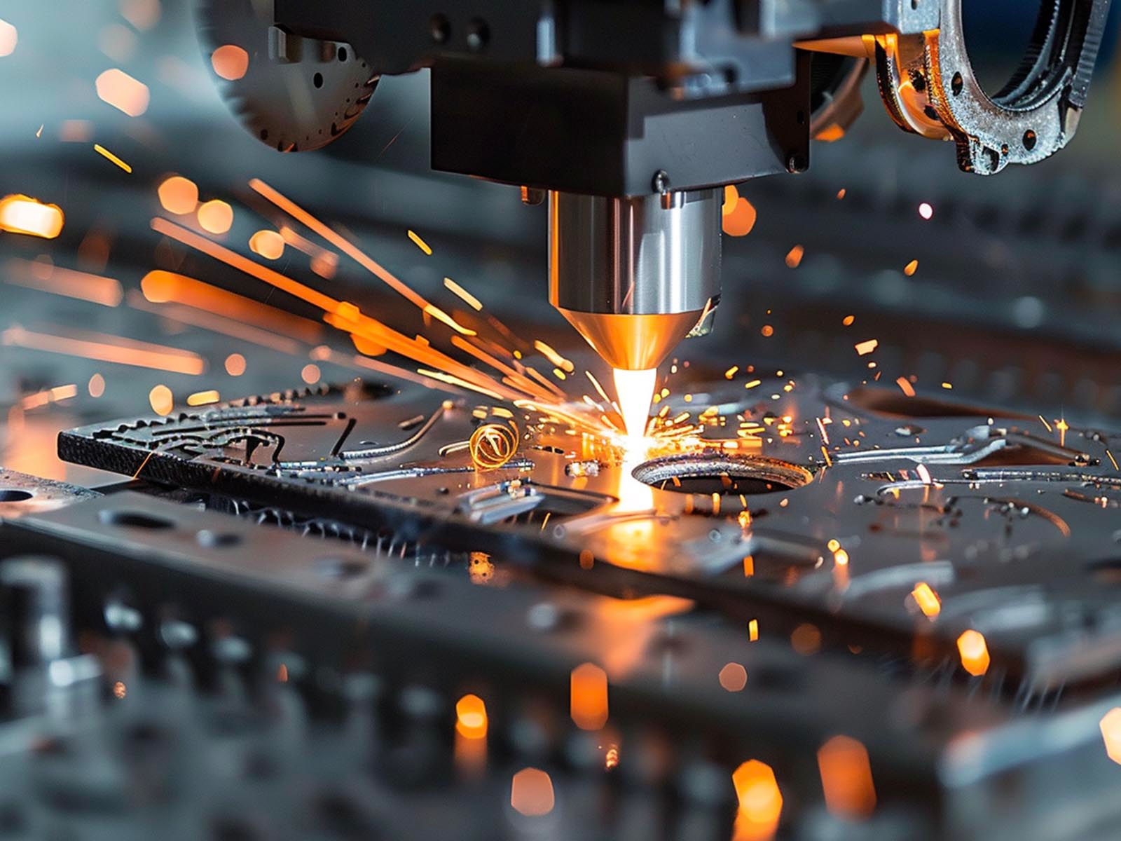
Kerf and Heat Dynamics: Kerf width and the Heat Affected Zone (HAZ) are the primary variables dictating dimensional accuracy; failing to compensate for them guarantees out-of-tolerance parts.
Thickness Dictates Precision: As material thickness increases, tolerance windows must widen due to beam divergence and thermal distortion.
Standard Baselines: Industry-standard laser cutting tolerances typically range from ±0.005” to ±0.010” for metals, and ±0.001” to ±0.005” for non-metals, heavily dependent on equipment calibration.
Geometry Constraints: Hole diameters must generally exceed material thickness, and narrow webs require specific spacing to prevent thermal warping.
Table of Contents
To specify accurate dimensions on a manufacturing drawing, you must first understand the physical phenomena occurring at the cutting nozzle. The most critical term is kerf. This refers to the actual material vaporized and removed by the beam. You cannot ignore it; if you do, your internal holes will be too large and your overall part footprint will be too small.
The Heat Affected Zone (HAZ) is the region immediately adjacent to the cut edge. While this area does not melt, the intense localized heat alters its microstructure. This often causes localized hardening or micro-warping, which wreaks havoc on secondary machining operations like tapping. Edge taper describes the angular deviation of the cut face from a true perpendicular plane. Because the beam focuses to a point and then diverges, the cut edge is rarely perfectly square. Finally, dross or burr refers to the re-solidified molten material clinging to the bottom edge of the cut. If the operator fails to deburr the part, this slag artificially inflates the measured dimension and prevents parts from mating flush.
A common pitfall in mechanical design is confusing machine accuracy with final part tolerance. Positional accuracy refers to the machine's mechanical ability to drive its cutting head to a specific coordinate on the bed. Repeatability is the machine's ability to return to that exact coordinate over multiple production cycles. A top-tier gantry system might boast a positional accuracy of ±0.001 inches. However, this does not mean the final cut part will hold a ±0.001-inch tolerance.
Final part tolerance is influenced by thermal expansion, material stress relief during the cut, and edge taper. A highly accurate machine guarantees consistent pathing, but achieving tight part tolerances requires rigorous DFM and proper material selection. We can break down these differences clearly:
Metric | Definition | Impact on Final Part |
|---|---|---|
Positional Accuracy | The exactness with which the machine head reaches a programmed CAD coordinate. | Ensures the cut path starts and stops in the correct physical location on the raw sheet. |
Repeatability | The ability to hit the exact same coordinate on subsequent runs. | Guarantees batch consistency. Part 1 and Part 1000 will have identical cut paths. |
Part Tolerance | The acceptable dimensional deviation of the finished, cooled physical part. | Determines if the part will actually fit into the final mechanical assembly. |
Kerf width is the primary dimensional offset you must manage during fabrication. When a beam penetrates a material, it burns away a specific width of stock. If a CAD file is processed without accounting for this missing material, the geometry fails. When optimizing Laser Cutting operations, programmers utilize CAM software to apply kerf compensation. This process offsets the cutting path by exactly half the kerf width.
The software pushes the beam outside the desired external boundary and inside the desired internal boundary. Kerf width fluctuates based on the power source, the focal length of the lens, and the specific material grade being processed. Fiber systems typically produce a narrower kerf than older CO2 systems, allowing for slightly tighter nesting and finer internal feature details. You must rely on the machine operator to dial in the exact kerf offset at the controller, as kerf changes slightly even between different batches of the same material alloy.
Introducing extreme heat into a localized area causes rapid thermal expansion followed by cooling and contraction. In thin sheet metals, this dynamic frequently results in warping, bowing, or twisting. The material literally pulls itself out of its specified dimensional tolerance as internal stresses release. The HAZ also complicates secondary operations. A hardened edge will deflect a drill bit or rapidly dull your tapping tools.
Furthermore, edge striations and dross impact the effective tolerance of a part during assembly. Two parts might measure within tolerance across their main bodies, but a microscopic burr prevents them from mating flush. Mitigation strategies include programming lead-in and lead-out cuts to keep piercing defects off the final part edge. Operators also optimize the cutting sequence to distribute heat evenly across the sheet, jumping from one quadrant to another rather than cutting sequentially. Utilizing pulse piercing reduces the initial heat input when blowing the first hole through thick plate.

Different metals react uniquely to concentrated thermal energy. Carbon steel is highly predictable. Operators typically cut it with an oxygen assist gas that creates an exothermic reaction, leaving a clean, smooth edge. Standard tolerances for thin carbon steel generally hold at ±0.005 inches. Stainless steel and aluminum require high-pressure nitrogen to blow away molten material and prevent oxidation. Because nitrogen cutting relies purely on thermal energy rather than an exothermic reaction, the heat input behaves differently.
Reflective metals like aluminum and copper present specific challenges. They naturally reflect the wavelength, particularly in CO2 systems. This requires higher power densities and perfect focal adjustments to prevent the beam from bouncing back into the cutting head. While modern fiber systems handle reflective metals efficiently, the aggressive nature of the cut can slightly degrade edge quality. You should expect a tolerance band closer to ±0.008 inches for these materials, depending heavily on the gauge.
Non-metallic materials introduce entirely different variables into the tolerance equation. Acrylic cuts exceptionally well, often yielding a flame-polished edge directly off the bed. However, it is highly susceptible to edge taper on thicker sheets. Polycarbonate absorbs heat rapidly. This leads to edge discoloration, bubbling, or melting, making tight tolerances difficult to hold consistently across a large batch.
Wood vaporizes and chars. The kerf width in wood varies wildly based on the moisture content, glue layers in plywood, and grain density of the specific board. Polyoxymethylene (POM), commonly known as Delrin, machines beautifully but requires rapid feed rates. If the head dwells too long in one spot, the edges melt and re-fuse behind the beam, destroying the dimensional integrity. Standard non-metal tolerances range from ±0.001 inches to ±0.005 inches. Achieving the tighter end of this spectrum requires pristine material conditions and exact focal calibration by the operator.
There is a direct, linear relationship between increasing material gauge and the necessary expansion of tolerance limits. As material gets thicker, the machine must slow down. This pumps more heat into the workpiece and increases thermal distortion. More importantly, the physics of the beam itself dictates tolerance loss.
The beam is not a perfect cylinder; it is shaped like an hourglass. It converges at the focal point and diverges as it exits the bottom of the cut. When cutting thick plate, this beam divergence creates a pronounced edge taper. A hole cut into a half-inch steel plate will measure slightly larger at the top surface than at the bottom surface. You must account for this taper when specifying tolerances for thick materials.
Material Gauge / Thickness | Typical Metal Tolerance | Edge Taper Risk | Design Recommendation |
|---|---|---|---|
20 Gauge (0.036") | ±0.005" | Minimal | Standard DFM rules apply. Excellent for precise interlocking joints. |
1/8" (0.125") | ±0.008" | Low to Moderate | Account for slight kerf variation. Press fits require prototyping. |
1/4" (0.250") | ±0.010" | Moderate | Taper becomes measurable. Do not specify tight interference fits without secondary machining. |
1/2" (0.500") | ±0.015" - ±0.020" | High | Expect significant taper. Holes will be conical. Plan for secondary drilling if precision is required. |
To establish a universal language for fabrication quality, the industry relies on ISO 9013. This is the international standard for thermal cutting classification. It provides a rigorous framework for evaluating cut quality beyond simple dimensional measurements. ISO 9013 categorizes tolerances into specific classes based on perpendicularity, mean dimensional deviations, and surface roughness.
Perpendicularity measures the squareness of the cut edge. Mean dimensional deviation tracks the overall accuracy of the part's footprint. Surface roughness measures the depth of the striations left on the edge by the assist gas and beam pulsing. By referencing specific ISO 9013 classes on engineering drawings, you remove ambiguity. Instead of vaguely requesting a clean cut, you specify an ISO 9013 Class 2 for perpendicularity. This forces the fabrication partner to calibrate their equipment to meet a mathematically defined standard.
Not all parts require aerospace-grade precision. Over-tolerancing is a primary driver of unnecessary manufacturing overhead. Standard commercial tolerances are highly efficient and perfectly suitable for the vast majority of structural brackets, enclosures, and internal chassis components. These tolerances allow the machine to run at optimal speeds, maximizing throughput and keeping production moving.
Precision tolerances are mandatory for medical devices, aerospace components, and complex kinematic assemblies. Achieving precision tolerances requires the operator to slow down the cut speed, perform more frequent nozzle centerings, and execute meticulous focal alignments. This reduction in cutting speed directly increases machine time. You must evaluate the trade-off carefully. Specify tight tolerances only on critical mating surfaces while allowing standard tolerances on non-critical exterior profiles.
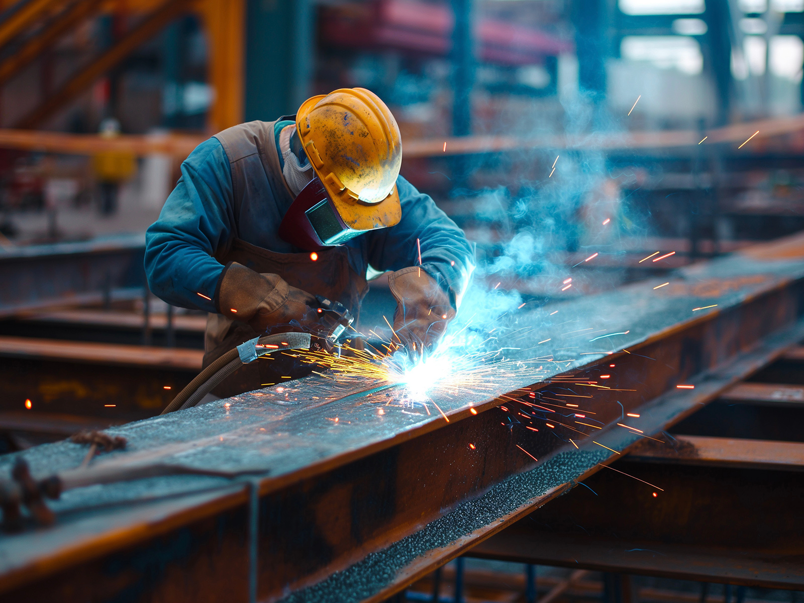
One of the most frequently violated DFM rules involves hole diameters. The foundational rule of thumb is the 1:1 ratio. A hole's diameter must be equal to or greater than the thickness of the material being cut. For example, cutting a 0.125-inch hole in a 0.250-inch plate violates this rule and invites failure.
When the machine attempts to cut a hole smaller than the material thickness, the intense heat cannot dissipate quickly enough through the small central slug. The material overheats, resulting in a blowout. You get a deformed, melted puddle rather than a precise circle. Hole tolerance deviations also impact downstream processes. Because of edge taper, the hole is slightly conical. If a PEM nut or a tapped thread requires a perfectly cylindrical wall, the taper compromises the hardware's holding force. While specialized systems utilizing water-assist or intricate pulse piercing routines can sometimes achieve micro-cutting exceptions below the 1:1 ratio, relying on this for standard production is highly risky.
The distance between cut features, known as web thickness, is another critical geometry constraint. If you place two parallel cuts too close together, the thin strip of material between them absorbs excessive heat from both passes. This causes the web to warp, lose its structural integrity, or vaporize entirely.
To prevent heat buildup, maintain a minimum web thickness equal to the material's gauge. For highly thermally conductive materials like aluminum, increasing the web thickness to 1.5 times the material gauge provides an added margin of safety. Proper edge proximity planning ensures the part remains flat and dimensionally stable throughout the cutting cycle.
Gantry systems excel at cutting straight lines and sweeping curves, but sharp internal corners present a distinct mechanical challenge. When the cutting head approaches a sharp 90-degree or acute internal angle, the machine's drive axes must rapidly decelerate to a complete stop before changing direction.
During this momentary dwell time, the beam continues to fire, pumping excess thermal energy into the corner. This localized melting causes the corner to blow out, resulting in an out-of-tolerance, rounded, or jagged radius. To maintain dimensional integrity, intentionally add small fillets to all internal corners. A 0.015-inch radius is usually sufficient. Alternatively, adding a small circular relief hole at the apex of the corner allows the head to maintain a constant velocity through the directional change, preventing heat accumulation.
Designing parts that assemble seamlessly without welding or mechanical fasteners requires mastering interference fits. A press fit relies entirely on friction. The dimensional overlap between the male and female parts must be calculated with extreme precision. Because of the inherent variables in kerf width and edge taper, achieving a reliable press fit straight off the machine bed is challenging.
The top face of a slot may measure perfectly, but the taper could cause the bottom of the slot to be too tight. You must design the interference fit based on the specific machine's known kerf and taper characteristics. Prototyping is absolutely essential. Run a test coupon with slots varying by increments of 0.002 inches. This allows your assembly team to find the exact friction fit required before committing to a full production run.
Tab and slot construction is a highly efficient method for creating self-fixturing sheet metal assemblies. However, if you draw the CAD lines with zero clearance, the parts will not fit together once the kerf is removed. You must apply a framework for offsetting CAD lines. If a tab is designed to be 0.500 inches wide, the corresponding slot must be designed slightly larger to accommodate the tab, plus an allowance for the kerf and standard slip clearance.
An advanced DFM technique is the node-based joint. Instead of relying on a tight tolerance along the entire length of the tab, add small, semi-circular bumps (nodes) to the sides of the tab. When inserted into the slot, these nodes crush or deform slightly, creating a rigid friction fit. This method absorbs minor tolerance deviations in the fabrication process, ensuring a tight joint without demanding impossible precision from the machine.
A fabrication vendor's stated tolerance capabilities are only as reliable as their equipment. When evaluating a partner, scrutinize the machinery on the floor. The wattage directly impacts cut quality. A high-wattage fiber system processes thicker materials at faster speeds, significantly reducing the HAZ and thermal distortion compared to a lower-wattage machine.
The technology type also matters. Fiber systems generally provide tighter tolerances on thin sheet metals, while CO2 systems historically yield smoother edges on thick acrylics and heavy steel plates. Furthermore, the age of the equipment and the vendor's maintenance schedule are critical. A machine with worn linear drives, dirty focal lenses, or an uncalibrated chiller unit will suffer from poor repeatability, regardless of its original factory specifications. Look at the slat beds; if they are covered in heavy slag, the sheet will not sit flat, destroying the focal distance.
Trusting a vendor requires verifying their quality control infrastructure. A reliable manufacturing partner must employ inspection tools capable of measuring beyond the resolution of standard hand calipers. To verify true positional accuracy, hole circularity, and edge taper, the vendor should utilize Coordinate Measuring Machines (CMMs) or high-resolution optical comparators.
For high-volume production runs, mandate First Article Inspection (FAI) reports. An FAI provides documented proof that a random sample from the initial production batch has been measured against all critical dimensions on the engineering drawing. This ensures the process is stable and the kerf offsets are correct before scaling up to full production.
Navigating vendor relationships requires the ability to spot technical red flags. If a fabrication shop promises to hold a ±0.001-inch tolerance on half-inch carbon steel straight off the bed without secondary CNC milling, they are overpromising. The physics of beam divergence makes that claim highly improbable in a standard production environment.
To mitigate implementation risks, proactively request a DFM review prior to issuing a purchase order. A competent vendor will analyze the CAD files, identify problematic hole ratios, flag narrow webs, and suggest specific kerf offsets. Aligning expectations during the quoting phase prevents costly disputes and rejected parts upon delivery.
Audit all CAD models to ensure internal hole diameters strictly adhere to the 1:1 material thickness ratio to prevent thermal blowouts.
Apply appropriate fillets or relief holes to all sharp internal corners to maintain constant cutting head velocity and prevent localized melting.
Define critical mating surfaces and specify the required ISO 9013 tolerance classes directly on the engineering drawings to remove vendor ambiguity.
Run physical test coupons for any tab-and-slot or press-fit joints to dial in the exact friction fit based on the machine's specific edge taper.
Submit the finalized files to a qualified fabrication partner for a comprehensive technical DFM review before authorizing full production.
Achieving consistent laser cutting tolerances depends not only on good design, but also on choosing a manufacturing partner with the right production and quality-control capabilities. DINGPRECISION supports precision manufacturing projects with a focus on accurate component production, helping customers turn engineering designs into reliable parts for prototyping and production applications.
A: The standard tolerance for cutting sheet metal generally falls between ±0.005” and ±0.010”. This range applies to common gauges of carbon steel, stainless steel, and aluminum. Thinner materials can often hold tighter tolerances closer to ±0.005”, while thicker plates require wider tolerance bands due to beam divergence and increased thermal distortion.
A: Kerf width represents the physical material vaporized by the beam. If a CAD file is cut exactly on the drawn line without software compensation, internal holes will be oversized and external dimensions undersized by half the kerf width. You must use CAM software to offset the cutting path to match the intended dimensional tolerance.
A: The industry-standard rule dictates that a hole's diameter should be equal to or greater than the material's thickness, known as the 1:1 ratio. Attempting to cut a hole smaller than the material thickness often results in blowout, where concentrated heat melts the surrounding metal, destroying the hole's dimensional accuracy.
A: Cut holes typically carry a tolerance of ±0.005” on thinner materials, expanding on thicker plates due to edge taper. Because the beam diverges, holes often become slightly conical, measuring larger at the top and smaller at the bottom. This taper directly impacts downstream processes like tapping or hardware insertion.
A: Yes, cut parts can achieve a press fit, but it requires precise kerf compensation and an understanding of the specific machine's edge taper. Engineers often design node-based joints by adding small, crushable bumps to tabs to create interference fits. Prototyping the joint on the exact material is necessary to dial in the friction.
A: Thicker materials require more power and slower cutting speeds, introducing more heat into the workpiece and causing greater thermal distortion. Additionally, as the beam penetrates deeper, it diverges from its focal point. This divergence creates a tapered edge, making it impossible to maintain the tight tolerances seen on thin sheet metal.
A: Accuracy refers to the machine's positional capability, meaning how precisely the cutting head can move to a specific coordinate. Tolerance is the acceptable dimensional deviation of the final cut part. A machine can be highly accurate, but if kerf width, thermal warping, and edge taper are not managed, the part will fall out of tolerance.


