
Views: 0 Author: Site Editor Publish Time: 2026-10-19 Origin: Site


Sheet metal fabrication is the highly specialized manufacturing process of transforming flat gauges of raw materials—such as steel, aluminum, or copper—into three-dimensional metal structures and components. Sourcing high-quality manufacturing requires moving beyond basic quotes and understanding the exact mechanics of how raw materials are transformed into finished components. Procurement and engineering teams often face cost overruns, delayed lead times, or tolerance failures because they lack visibility into the specific fabrication stages and the inherent limitations of different manufacturing techniques. By breaking down the step-by-step manufacturing process of sheet metal parts, buyers can accurately evaluate vendor capabilities, optimize designs for manufacturability (DFM), and mitigate production risks before committing to a production run. Understanding these mechanical transitions prevents late-stage redesigns and ensures structural integrity across high-volume manufacturing cycles.
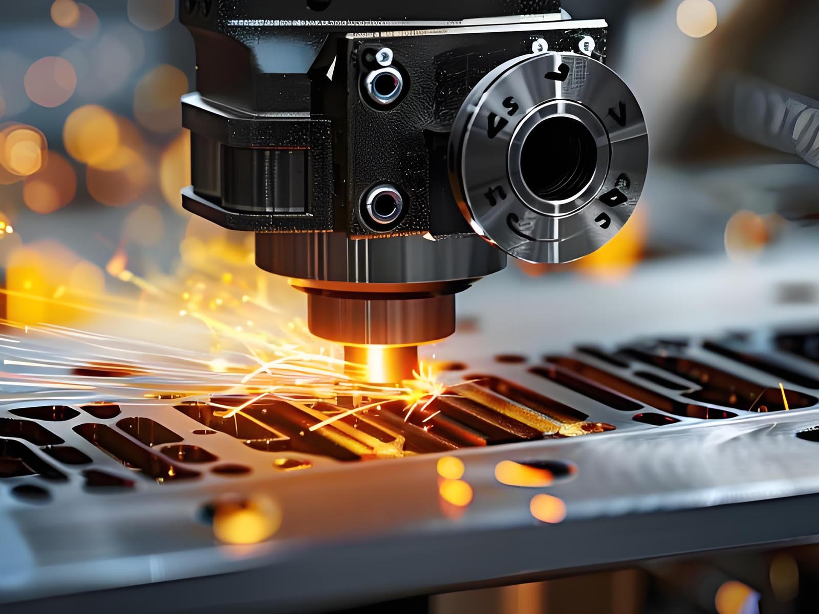
Design dictates cost: Upfront Design for Manufacturability (DFM), precise material selection, and efficient flat-pattern nesting are the primary drivers of unit economics and structural viability.
Process selection impacts tolerances: The choice between laser cutting, punching, and waterjet directly affects edge quality, thermal distortion, and final dimensional accuracy.
Forming introduces variables: Bending and deformation require specific expertise to manage material springback and prevent micro-fractures in complex sheet metal parts.
Quality control is continuous: Reliable fabrication partners do not relegate inspection to the final step; they integrate dimensional verification and compliance checks at every transition point.
Table of Contents
Manufacturing begins inside digital environments where engineers design three-dimensional models using advanced CAD software. Because fabrication requires flat sheets of metal, the software must unfold these 3D models into 2D flat patterns. This translation process demands precise mathematical calculations. When a press brake bends metal, the material stretches on the outside radius and compresses on the inside radius. The neutral axis inside the material shifts during this deformation. Engineers call this shift the K-factor. Software models must account for bend allowances, K-factors, and specific material thickness. Ignoring these variables results in flat patterns that yield incorrect final dimensions on the shop floor. Accurate unfolding ensures the physical part matches the digital intent perfectly.
Raw material represents a massive portion of fabrication expenses. Manufacturers use dynamic nesting software to arrange multiple 2D flat patterns onto a single raw sheet. The goal involves maximizing material yield and minimizing scrap. Advanced algorithms rotate and interlock different shapes, fitting parts together like a complex puzzle while accounting for the kerf width of the cutting laser. Efficient nesting directly reduces the per-unit cost of Sheet Metal Parts. High-volume runs benefit significantly from optimized layouts. Less wasted material translates to lower overall production expenses. Vendors demonstrating strong nesting capabilities provide better value, as they extract the maximum number of components from every standard sheet of metal.
Choosing the right metal dictates structural integrity and manufacturing viability. Different alloys behave differently under cutting and forming stresses. You must evaluate materials across multiple dimensions to ensure they meet the mechanical requirements of the final assembly.
Material | Key Characteristics | Common Applications | Manufacturing Considerations |
|---|---|---|---|
Aluminum (5052-H32, 6061-T6) | Lightweight, high corrosion resistance, excellent strength-to-weight ratio. | Aerospace, electronics enclosures, automotive components. | 6061 is prone to cracking on tight bend radii. 5052 forms much easier. |
Stainless Steel (304, 316) | Exceptional corrosion resistance, high tensile strength, aesthetic finish. | Medical devices, food processing equipment, marine hardware. | Work-hardens quickly. Requires high tonnage for bending operations. |
Cold-Rolled Steel (CRS) | Cost-effective, uniform surface finish, tight thickness tolerances. | Appliance panels, industrial brackets, furniture frames. | Requires surface finishing (painting/plating) to prevent rapid rusting. |
Copper (C110) | Superior electrical and thermal conductivity, highly malleable. | Busbars, electrical contacts, heat exchangers. | Soft material requires careful handling to prevent surface scratches. |
Engineers must balance yield strength against raw material costs. High-tensile materials resist deformation but demand heavier machinery and cause faster tooling wear. Softer metals form easily but may lack structural rigidity for load-bearing applications. Environmental exposure requirements often dictate the final choice, pushing designers toward stainless steel or treated aluminum for outdoor use.
Early DFM reviews prevent costly rework and tooling delays. Designers often make common mistakes that complicate fabrication. Placing holes too close to bend lines causes hole distortion during forming. Ignoring standard tooling sizes forces vendors to order custom dies, adding weeks to lead times. Designing impossible bend sequences creates manufacturing bottlenecks where the part collides with the press brake. A thorough DFM review catches these flaws before cutting begins. Fabricators analyze the design and suggest minor modifications. To mitigate risks, engineering teams should follow these specific checks:
Verify all hole diameters exceed the material thickness to prevent punch breakage during CNC punching.
Ensure hole-to-bend distances measure at least 1.5 times the material thickness plus the bend radius.
Standardize bend radii across the entire part to minimize press brake setup changes and reduce labor time.
Align flat patterns so that critical bends run perpendicular to the material grain direction.
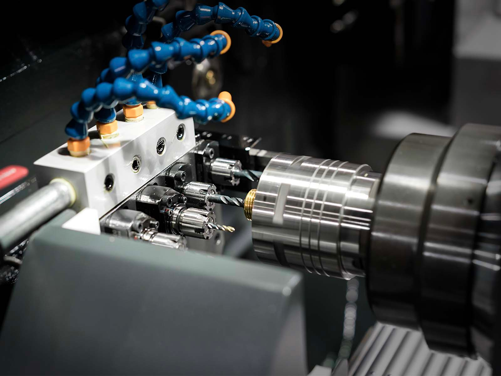
Transforming a flat sheet into distinct parts requires precise cutting technologies. Manufacturers select methods based on material type, thickness, and volume requirements. Each technology offers distinct advantages and limitations.
Laser cutting offers high precision and speed for intricate designs. A focused beam of light melts and vaporizes the metal, while high-pressure assist gas (like nitrogen or oxygen) blows the molten material away. Modern fiber lasers cut thin metals incredibly fast and handle complex geometries with ease. However, lasers generate intense heat. This creates a heat-affected zone (HAZ) along the cut edge. The HAZ can alter the microstructure of certain alloys, causing localized hardening that makes subsequent bending more difficult. It may also cause minor thermal distortion on very thin sheets.
Waterjet cutting solves the thermal distortion problem entirely. It uses a high-pressure stream of water mixed with abrasive garnet. This cold-cutting process generates zero heat. It represents the ideal solution for thick materials or heat-sensitive metals. Waterjets cut through thick stainless steel, titanium, or even ballistic armor effortlessly. They provide superior edge quality without metallurgical changes. The primary trade-off involves speed. Waterjet cutting runs significantly slower than laser cutting and generally costs more per inch of cut.
CNC punching remains highly cost-effective for high-volume runs. A mechanical or hydraulic press forces a hardened steel punch through the metal into a die. It excels at creating uniform hole patterns rapidly. Punch presses offer a unique dual capability. They perform minor forming operations during the cutting phase. Specialized tooling can create louvers, dimples, countersinks, or extruded holes without moving the part to another machine. Punching struggles with complex, sweeping curves, working best for geometric shapes and perforated designs.
The initial cutting phase always leaves imperfections. Lasers create dross or slag on the bottom edge. Punching leaves sharp burrs and micro-fractures. Waterjets can leave frosted or slightly striated edges on thicker plates. The cutting phase must be immediately followed by deburring. Operators use automated timesaver machines with wide abrasive belts, vibratory tumblers, or manual dual-action sanders to remove sharp edges. Proper edge preparation ensures safe handling during downstream processes. It also prevents stress concentrations during the bending phase. Micro-cracks often propagate from sharp, jagged edges when metal bends. Smooth edges guarantee structural integrity.
The chosen cutting method establishes the baseline tolerance for the entire project. Laser cutting typically holds tolerances around ±0.005 inches. Punching holds similar tolerances depending on tooling wear and machine calibration. Waterjet tolerances vary based on cutting speed and material thickness, often ranging from ±0.005 to ±0.015 inches. Edge finishes impact downstream assembly. Rough edges interfere with tight-fitting mating parts or robotic welding fixtures. Buyers must set realistic expectations for edge finishes and specify critical dimensions early to guide the cutting technology selection.
Flat parts require bending to achieve three-dimensional shapes. Operators use CNC press brakes for this task. A press brake clamps the metal between a top punch and a bottom V-die. Hydraulic or electric rams force the punch downward, creating precise bends to form the nearly finished part. Fabricators utilize three primary bending methods depending on the required accuracy and available machinery.
Air Bending: The punch presses the metal into the V-die without touching the bottom. The metal rests on three points: the punch tip and the two top edges of the V-die. This method requires less force and allows operators to achieve multiple angles from one die set by adjusting the punch depth.
Bottoming: The punch forces the material fully into the V-die, matching the angle of the tooling. This approach offers higher accuracy and consistency across large runs. It requires significantly more tonnage than air bending.
Coining: The machine stamps the metal with extreme force. The punch tip penetrates the neutral axis of the material. This eliminates springback entirely and provides exact angles. Coining demands massive machinery, high tonnage, and causes rapid tooling wear.
Metal possesses inherent elasticity. When a press brake bends a part, the material attempts to return to its original flat state upon release. Industry professionals define this reaction as springback. Different materials react differently to deformation. High-tensile steel exhibits severe springback. Soft aluminum shows very little. Experienced fabricators calculate over-bending to achieve the target angle. If the blueprint requires a 90-degree bend in 304 stainless steel, the operator might push the punch to 87 degrees. The material springs back exactly three degrees to hit the target. Accurately predicting springback across different alloys demonstrates true vendor expertise.
Forming introduces severe physical stress. Material cracking at tight bend radii represents a major implementation risk. Hardened metals fracture if bent too sharply. Engineers must specify minimum bend radii based on material thickness and alloy type. Grain direction in the raw sheet metal also dictates structural integrity. Rolling mills create a visible grain structure in flat sheets. Bending parallel to the grain often causes cracking, especially in aluminum alloys like 6061. Fabricators must orient the flat pattern during the nesting phase so bends run perpendicular to the grain. This orientation prevents fractures and ensures strong Sheet Metal Parts.
Many components require threads for final assembly. Tapping thin metal often provides insufficient thread engagement, leading to stripped threads in the field. Fabricators solve this by installing self-clinching fasteners, standoffs, and threaded inserts (commonly known as PEM hardware). Operators use specialized hydraulic presses with auto-feed bowls to squeeze hardware into pre-punched holes. The fastener displaces the sheet metal under high tonnage. The metal flows cold into an annular recess on the hardware, permanently locking the fastener in place. Facilities perform this step before final assembly. Inserting hardware on flat components ensures proper seating, flush finishes, and prevents access issues inside tight enclosures.
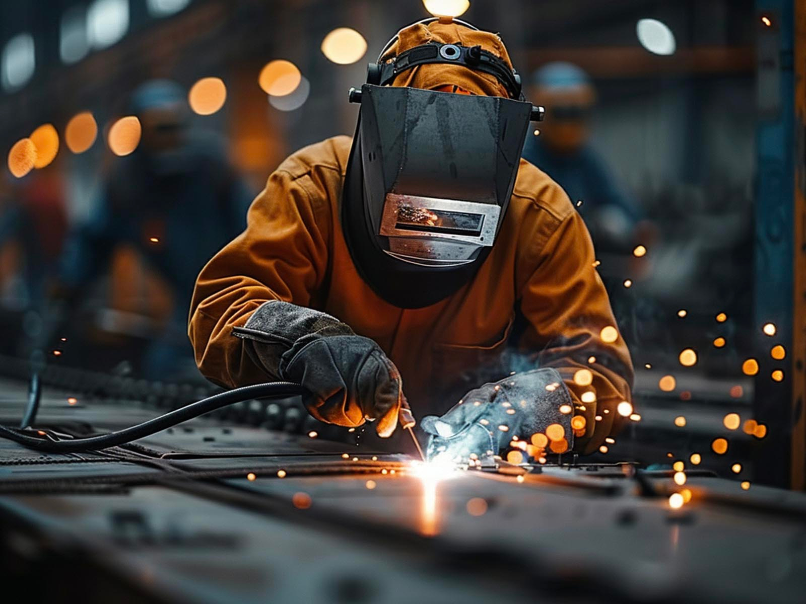
Transforming individual pieces into complex assemblies often requires welding. Fabricators deploy different techniques based on material, thickness, and structural needs.
TIG Welding (Gas Tungsten Arc Welding): Offers high precision and exceptional aesthetic finishes. Welders control the heat input meticulously using a non-consumable tungsten electrode. It works perfectly for thin metals, stainless steel, and visible joints on medical or food-grade equipment. TIG welding requires immense skill and runs slowly.
MIG Welding (Gas Metal Arc Welding): Prioritizes speed and penetration. A continuously fed wire acts as both the electrode and the filler metal. MIG suits thicker materials and heavy structural frames. It leaves a larger weld bead and requires more post-weld grinding to achieve a smooth finish.
Spot Welding: Provides fast, localized joining for overlapping sheets. Copper electrodes clamp the metal and pass a high electrical current. Resistance generates localized heat, melting the metal and fusing the sheets together instantly without filler material.
Welding introduces the risk of heat distortion. Intense thermal cycles cause metal to warp and pull out of tolerance. Fabricators use heavy steel fixturing and toggle clamps to hold parts rigidly. They deploy copper heat sinks to draw thermal energy away from critical surfaces. These mitigation strategies keep assemblies dimensionally accurate.
Welding destroys pre-coated materials and struggles with dissimilar metals like joining aluminum to steel. Cold joining alternatives provide robust structural assembly without heat. Fabricators evaluate the use of structural blind rivets, solid rivets, and industrial adhesives (like VHB tape or structural epoxies). Rivets pull panels together tightly and handle shear loads well. High-strength epoxies distribute stress evenly across entire overlapping seams rather than concentrating it at point loads. Cold joining acts as the perfect solution for galvanized steel or pre-painted aluminum. It maintains the surface finish and eliminates thermal warping risks completely.
Raw metal requires protection from environmental degradation. Surface finishing provides both functional durability and aesthetic appeal. Fabricators break down common treatments into several categories based on the base material and end-use environment.
Powder Coating: Operators spray electrostatically charged dry powder onto grounded parts. Ovens bake the parts at high temperatures, melting the powder into a hard, durable skin. It resists chipping, scratching, and UV fading far better than traditional wet paint.
Anodizing: An electrochemical process used primarily for aluminum. It thickens the natural oxide layer on the metal surface. Anodizing provides extreme corrosion resistance, increases surface hardness, and allows for vibrant color dyes that will not peel.
Plating: Zinc or chromate plating adds a thin sacrificial layer over steel. The plating corrodes before the underlying base metal. It offers excellent functional protection for internal components and chassis.
Passivation: A chemical treatment for stainless steel. Acid baths remove free iron and machining contaminants from the surface. This enhances the passive chromium oxide layer, maximizing rust resistance without changing the part's appearance.
Finishing impacts the final dimensions of fabricated components. Powder coating adds physical thickness to surfaces. A standard powder coat adds between 0.002 and 0.004 inches of material per side. This buildup easily throws tight-tolerance holes out of spec or prevents mating parts from sliding together. Buyers must account for finish thickness during the design phase. You must specify masking requirements clearly on shop drawings. Masking protects conductive areas for electrical grounding. It keeps threads clean on inserted hardware using silicone plugs. Proper masking instructions prevent assembly failures and eliminate the need to chase threads manually after coating.
Reliable manufacturing demands rigorous metrology. Fabricators verify dimensional accuracy using advanced tools rather than relying solely on tape measures and calipers. Coordinate Measuring Machines (CMM) use sensitive touch probes to map the physical geometry of a part in three-dimensional space. They compare the physical dimensions directly against the original 3D CAD model. Optical comparators project magnified silhouettes of small parts onto a screen, allowing inspectors to measure complex profiles and tight radii easily. First Article Inspection (FAI) plays a critical role in this phase. Inspectors thoroughly measure the very first production unit and document every dimension. FAI validates the entire manufacturing process, tooling setup, and CNC programming before full-scale production begins.
Vendor trustworthiness heavily relies on established quality management systems. ISO 9001 certification proves a fabricator maintains documented, repeatable processes and a commitment to continuous improvement. Aerospace applications demand AS9100 certification, which includes stricter risk management protocols. Medical device components require ISO 13485 compliance. These standards enforce strict traceability. Fabricators must provide material test reports (MTRs) upon request. MTRs trace the raw sheet metal back to the original steel mill. They verify the exact chemical composition, heat lot, and mechanical properties of the alloy. Traceability protects buyers from counterfeit or substandard materials that could fail catastrophically in the field.
Selecting a vendor requires looking beyond prototype capabilities. You must evaluate whether a vendor's equipment aligns with your volume requirements. Assess their material handling infrastructure. Automated sheet loaders feed raw material into lasers continuously, enabling lights-out manufacturing and massive throughput. Robotic welding cells handle high-volume assemblies with perfect consistency and speed. Vendors lacking automation struggle to scale when your product takes off. Manual loading and manual welding create severe production bottlenecks. Evaluate their machinery to ensure they can meet your lead times during peak demand without sacrificing quality.
A successful prototype means nothing if production scaling fails. Evaluate how seamlessly a vendor transitions a prototype into a high-volume run. Some vendors use soft tooling or manual processes for prototypes to save time. Scaling up then requires complete re-tooling, new programming, or redesigns. The best partners use production-intent processes from day one. They cut and bend prototypes on the exact CNC machines slated for the final run. This guarantees the prototype accurately reflects high-volume production reality. It eliminates nasty surprises, tolerance shifts, and unexpected costs during the transition phase.
The initial quoting phase reveals a vendor's true competence and attention to detail. Watch for critical red flags. Avoid vendors who do not request clarification on ambiguous tolerances. A silent vendor often assumes standard commercial tolerances, which may ruin your precision assembly. Beware of fabricators who ignore DFM feedback. A proactive partner always suggests design tweaks to save money, reduce scrap, or speed up assembly. Finally, reject quotes that fail to specify the exact grade of raw material. Vague material descriptions allow vendors to substitute cheaper, weaker alloys to pad their margins. Demand absolute transparency in every estimate.
Manufacturing sheet metal parts is a highly interdependent process where decisions made during blueprinting, cutting, and bending exponentially impact assembly and finishing. Buyers must select partners who demonstrate transparent DFM capabilities, possess the right mix of cutting and forming technologies for the specific material, and enforce rigid quality control at every stage. Take the following actions to secure high-quality fabrication and streamline your procurement process:
Finalize your 3D CAD models and generate accurate 2D flat patterns with clearly defined bend lines.
Define your critical tolerances explicitly on all shop drawings to prevent vendor assumptions.
Request a comprehensive DFM review alongside your initial manufacturing quote to identify cost-saving opportunities.
Require material test reports (MTRs) and First Article Inspection (FAI) documentation for all production runs.
For projects that require reliable manufacturing support from prototype development through production, DINGPRECISION provides precision manufacturing and sheet metal fabrication solutions for a range of custom component requirements. By combining manufacturing capabilities with attention to dimensional accuracy, material selection, and production quality, DINGPRECISION supports customers in turning engineered designs into consistent, production-ready parts.
A: CNC punching is generally the most cost-effective method for high-volume production, especially for parts with uniform hole patterns. For low-to-medium volumes or highly complex geometries, fiber laser cutting offers the best balance of speed, precision, and low setup costs without requiring custom tooling.
A: Nesting is the process of using software to arrange multiple 2D flat patterns onto a single sheet of raw material. By interlocking parts tightly and accounting for the cutting tool's kerf, nesting maximizes material yield and minimizes scrap. This directly reduces the raw material cost per unit.
A: Thicker materials require significantly more tonnage to bend. They also demand larger V-dies and larger minimum bend radii to prevent cracking on the outside edge. Thicker metals exhibit different springback characteristics, requiring operators to adjust over-bending calculations carefully to hit target angles.
A: Standard commercial tolerances for sheet metal fabrication generally fall around ±0.010 to ±0.015 inches for bending and forming operations. Laser cutting can achieve tighter tolerances of ±0.005 inches. Tighter tolerances are possible but usually require specialized tooling and increase manufacturing costs.
A: Sheet metal acquires a grain structure during the rolling mill process. Bending metal parallel to this grain increases the risk of fracturing and cracking, especially in harder alloys. Fabricators must orient flat patterns so that critical bends run perpendicular to the grain for maximum structural integrity.
A: Laser cutting uses a focused beam of light to melt through metal, offering extreme precision for complex curves without custom tooling. CNC punching uses mechanical force to drive a steel tool through the metal, which is faster for repetitive hole patterns and allows for minor 3D forming like louvers.


