
Views: 0 Author: Site Editor Publish Time: 2026-10-08 Origin: Site


The disconnect between an idealized CAD model and the physical realities of the shop floor often results in unexpected delays, compromised structural integrity, or extended lead times. Specifying the wrong fabrication method directly impacts product viability. Failing to account for tooling requirements, material behaviors, and volume scaling creates downstream failures. Navigating these challenges requires a rigorous evaluation of available techniques. This guide breaks down core Sheet Metal Fabrication Processes. We detail technical capabilities, machinery, cost structures, and implementation risks. You will learn how to support data-driven sourcing and design decisions effectively. Understanding these methods ensures your designs translate from digital concepts to physical components without requiring constant rework.
Process selection dictates unit economics: Scaling from 1 to 10,000+ parts requires strategic shifts. High-volume production justifies the heavy upfront tooling costs of stamping or roll forming, while low-to-medium volumes rely on the flexibility of laser cutting and press brake bending.
Tolerances drive costs exponentially: Specifying tighter tolerances than functionally necessary restricts process options and increases scrap rates and inspection costs.
Design for Manufacturability (DFM) is non-negotiable: Early alignment between design intent and specific fabrication capabilities prevents costly secondary operations and mitigates risks like heat distortion or material fracturing.
Finishing is a functional requirement, not just aesthetic: Surface treatments must be evaluated for environmental compliance, corrosion resistance, and their impact on final part dimensions.
Table of Contents
Defining the functional requirements of a part is the first step in any manufacturing project. You must establish clear success criteria before selecting a fabrication method. Consider the load-bearing needs of the final structure. Will the component face static loads like a server rack, or dynamic loads like a vehicle chassis? Environmental exposure also dictates process selection. Parts facing marine environments require different handling and material grades than indoor enclosures. Lifecycle expectations further refine your choices. You must transform raw metal into usable structures while meeting these baseline functional demands. Failing to define these criteria early leads to over-engineering or premature part failure in the field.
Analyzing breakeven points determines how you scale production. The journey from prototyping 1 to 50 parts looks vastly different than mass-producing 10,000 components. Low-tooling methods like laser cutting carry higher variable costs per unit. They offer immense flexibility for design iterations because you do not need to machine physical dies. Conversely, high-tooling methods like hard tooling stamping require significant upfront investment. However, they deliver exceptionally low variable costs at scale. You must calculate the exact volume tier where stamping becomes more economical than CNC punching. This calculation prevents capital waste on unnecessary tooling for low-volume runs.
Material properties dictate which forming and cutting processes remain viable on the shop floor. Yield strength determines the force required to permanently deform the metal. Ductility indicates how much a material can stretch before fracturing. Work hardening occurs when metals become brittle during repeated forming operations. You must match these properties to your chosen Sheet Metal Fabrication Processes. For example, forming 5052-H32 aluminum offers excellent bendability for complex enclosures. Attempting the same tight-radius bends on 6061-T6 aluminum often results in immediate cracking. High-strength steel requires immense press brake tonnage compared to standard A36 mild steel. Always verify material compatibility before finalizing your flat patterns.
Material Grade | Formability | Weldability | Common Applications |
|---|---|---|---|
304 Stainless Steel | Good | Excellent | Food processing equipment, medical devices |
5052-H32 Aluminum | Excellent | Good | Electronic enclosures, marine hardware |
6061-T6 Aluminum | Poor (Prone to cracking) | Good | Structural brackets, machined components |
A36 Mild Steel | Good | Excellent | Heavy structural frames, industrial brackets |
Establishing realistic baseline tolerances prevents exponential cost increases. A tolerance of +/- 0.005 inches requires precision machinery, frequent calibration, and rigorous manual inspection. A standard tolerance of +/- 0.030 inches accommodates standard fabrication variations easily. You must understand how cumulative tolerances stack across multiple steps. A part cut on a laser, bent on a press brake, and welded will accumulate variance at each stage. Specifying unnecessarily tight tolerances restricts your process options. It also increases scrap rates and drives up unit costs. Apply tight tolerances only to critical mating surfaces and leave non-critical dimensions loose.
Shearing provides rapid, straight-line cutting using guillotine shears. It excels at slicing large master sheets into manageable blanks for downstream operations. Operators use backgauges to ensure repeatable cut dimensions. Notching removes material from corners to prevent overlap during subsequent bending operations. This method is highly cost-effective for blanking standard rectangular shapes. It prepares flat patterns quickly for press brake operators. However, shearing faces strict geometric limitations. It remains limited to straight lines and exterior edges. You cannot produce internal holes or complex curves using this method. Edge quality may also exhibit slight burrs requiring secondary finishing.
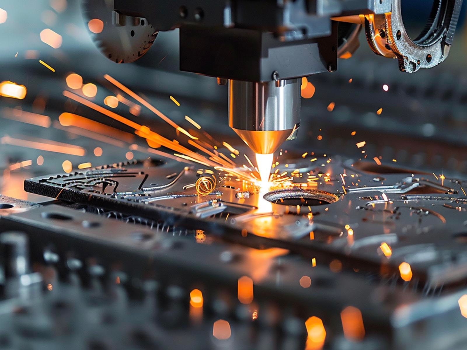
Laser cutting delivers high precision and handles complex geometries effortlessly. Modern fiber lasers cut through thin-gauge metals at incredible speeds. It requires minimal setup time since it uses no physical cutting dies. This makes it the premier choice for low-to-medium volumes and rapid prototyping. Engineers rely on laser cutting for intricate hole patterns and organic shapes. The primary trade-off involves per-part cycle time on parts with hundreds of holes, where a punch press might be faster. Additionally, the thermal process creates a Heat-Affected Zone (HAZ) along the cut edge. This localized heating hardens the edge, complicating secondary machining or tapping operations.
Waterjet cutting utilizes a high-pressure stream of water mixed with abrasive garnet. It is a completely cold cutting process. This capability allows it to handle extreme material thicknesses easily, often cutting through several inches of solid steel. It also excels at cutting highly reflective metals like copper and brass, which often challenge traditional CO2 lasers. Waterjet is ideal when thermal distortion or a HAZ is entirely unacceptable. The aerospace and medical industries frequently specify this method to preserve material temper. The main drawbacks include slower cutting speeds. It also carries higher operational costs per inch compared to plasma or laser alternatives.
Plasma cutting offers high-speed processing for thick metal plates. It handles heavy steel and aluminum efficiently by blowing ionized gas at high velocities. This method proves highly cost-effective for heavy industrial components. It works best when pristine edge quality remains a secondary concern. Structural base plates and heavy equipment brackets are typical applications. The trade-offs include a significantly wider kerf than laser cutting. Plasma also generates a larger HAZ due to the intense thermal energy. The resulting edge finish is generally rougher, often leaving dross on the bottom edge. Parts require secondary deburring or grinding before welding or assembly.
CNC punching enables rapid processing of standard geometries. A turret press rapidly punches holes, louvers, and straight cuts using a rotating carousel of hard tooling. This process is highly scalable for medium-to-high production volumes. It also allows for 3D forms like dimples, knockouts, and countersinks within the same setup. This eliminates the need for secondary forming operations. However, CNC punching requires specific physical tooling for non-standard shapes. Custom tools add lead time and upfront costs. Tooling wear also impacts long-term tolerance consistency. Regular maintenance and tool sharpening are mandatory for maintaining part quality.
Cutting Process | Best For | Key Advantage | Primary Limitation |
|---|---|---|---|
Shearing | Straight-line blanking | Extremely fast and cost-effective | Cannot cut internal holes or curves |
Laser Cutting | Complex geometries, prototyping | High precision, zero tooling cost | Creates a Heat-Affected Zone (HAZ) |
Waterjet Cutting | Thick plates, heat-sensitive parts | No thermal distortion (cold process) | Slower speeds, higher operational costs |
Plasma Cutting | Heavy industrial components | Fast cutting on very thick metals | Wide kerf and rough edge finish |
CNC Punching | High volumes with standard holes | Can create 3D forms (louvers, dimples) | Requires physical tooling for custom shapes |
Press brake bending provides versatile linear bending capabilities. Operators use standard V-dies and punches to form angles. It remains the industry standard for manufacturing enclosures, brackets, and chassis. Air bending requires less tonnage and offers flexibility in bend angles because the punch does not force the material all the way to the bottom of the die. Bottoming and coining force the material fully into the die for higher precision, requiring significantly more machine tonnage. Implementation risks center around material springback. Springback variations occur across different material batches, requiring operator adjustments. You must also account for minimum flange length limitations. Flanges too short will slip into the V-die during the bending cycle.
To ensure repeatable press brake operations, operators follow a strict setup sequence:
Verify the material gauge and grain direction against the engineering drawing.
Select the appropriate punch radius and V-die opening based on the material thickness.
Calculate the required tonnage to prevent overloading the machine hydraulics.
Program the backgauge coordinates to establish the exact bend line location.
Perform a test bend on scrap material to measure and compensate for springback.
Specialty forming techniques manipulate metal without standard linear dies. Beading adds structural rigidity to panels without increasing overall material thickness. Flanging creates reinforced edges for assembly. Shrinking and stretching allow fabricators to produce complex, curved profiles using specialized jaw tools. These methods are common for lightweight structural components. Aerospace applications and custom enclosures rely on them for high stiffness-to-weight ratios. The implementation risks are notable. These techniques require highly specialized machinery like English wheels or power hammers. They can also induce localized material fatigue if the metal is over-worked during the forming process.
Stamping delivers high-speed, single-stroke forming of complex shapes. A mechanical or hydraulic press forces a custom die into the sheet metal. It represents the definitive choice for production volumes exceeding 10,000 units. Progressive stamping presses can execute multiple operations, including blanking, piercing, and forming, simultaneously as the metal strip feeds through the machine. The primary trade-off involves prohibitive upfront die costs. Developing hard tooling requires extended lead times and significant capital. Design changes post-tooling are highly expensive. You must lock in your final design completely before initiating the stamping die manufacturing process.
Roll forming is a continuous bending operation. Flat sheet metal feeds from a coil through a series of mated roll dies. Each stand incrementally bends the metal until it reaches the desired cross-section. This process is superior for manufacturing long, uniform parts like structural channels, roofing panels, and tracks. It offers incredible production speeds once the line is running. The main trade-offs include high setup costs and extensive tooling requirements. Roll forming is strictly limited to specific linear profiles. It cannot produce parts with varying cross-sections or complex 3D forms outside the linear axis.

Hardware insertion involves pressing specialized fasteners into pre-punched holes. This process provides strong, reusable, load-bearing threads in thin sheet metal. It is standard for electronic enclosures, PCBs, and structural assemblies. Often, the base metal is simply too thin to tap traditional threads. Clinch fasteners displace the host material using a specialized anvil and punch. The metal cold-flows into the fastener's undercut, locking it securely in place. Implementation risks require strict DFM adherence. You must specify precise hole sizing. You must also maintain adequate edge-distance clearances. Placing hardware too close to an edge causes material bulging or catastrophic hardware failure.
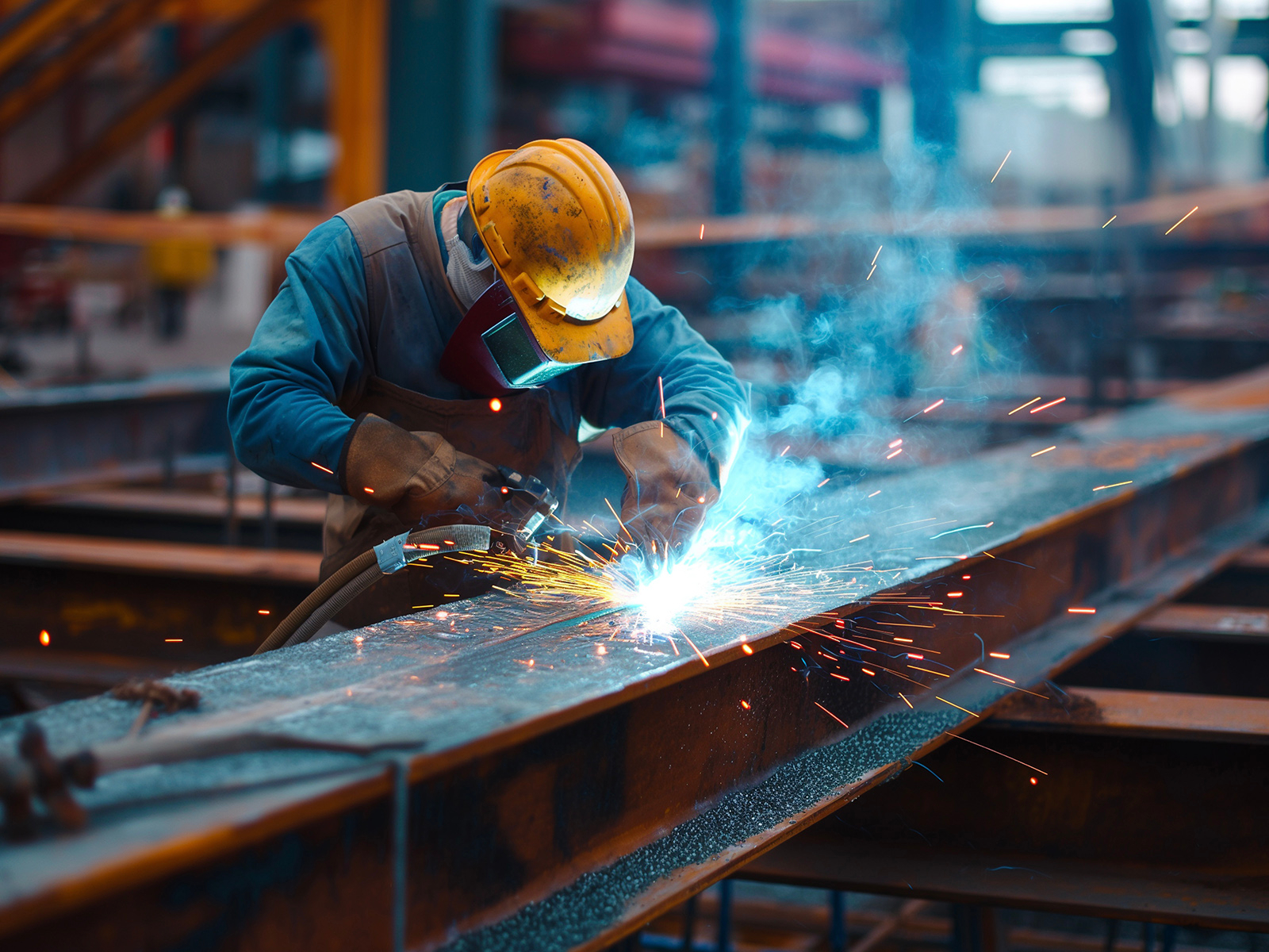
Welding creates permanent, high-strength structural joints. TIG (GTAW) welding offers exceptional precision and aesthetic control, ideal for visible seams on stainless steel. MIG (GMAW) welding provides speed and deep penetration for thicker structural components. Spot welding rapidly joins thin-gauge overlapping seams without filler material by passing an electrical current through the metal. Laser welding delivers deep, narrow welds with minimal heat input. Implementation risks include severe heat distortion and warping. Burn-through is a constant threat on thin gauges. Welding also requires highly skilled labor. Post-weld grinding and polishing add significant time and cost to the final assembly.
Mechanical fastening joins components without introducing heat. It is perfect for joining dissimilar materials, like aluminum to steel, where welding is impossible. It also protects pre-coated or pre-painted metals from thermal damage. This method is ideal for assemblies requiring future maintenance or complete disassembly. Blind riveting provides a permanent mechanical joint where welding would destroy delicate surface finishes. The trade-offs include added component weight from the fasteners themselves. It also requires overlapping joint designs. Precise hole alignment across multiple mating parts is mandatory to ensure successful mechanical assembly.
Adhesive bonding utilizes industrial-grade epoxies and VHB tapes to join sheet metal. This method provides even stress distribution across the entire joint area, unlike spot welding which concentrates stress. It offers excellent vibration dampening and creates completely invisible joints. Adhesive bonding is best suited for lightweight enclosures and aesthetic architectural panels. However, implementation risks are stringent. The process requires meticulous surface preparation to ensure proper adhesion. Any oil, scale, or dust will compromise the bond. Adhesives are also sensitive to environmental degradation. Extreme temperature fluctuations and high humidity can weaken the joint over time.
Surface finishing protects raw metal from corrosion while enhancing aesthetics. Powder coating applies a dry powder electrostatically, which is then cured under heat in an oven. It offers superior durability, excellent scratch resistance, and robust edge coverage. It is the industry standard for rugged metal enclosures. Wet painting utilizes liquid solvents. It is required for parts that cannot withstand the high temperatures of a powder curing oven. Wet paint also allows for highly customized color matching. However, wet paint generally chips easier, requires longer drying times, and emits volatile organic compounds (VOCs) during application.
Plating and anodizing alter the surface chemistry of the metal. Zinc or nickel plating provides excellent corrosion resistance for steel components. It acts as a sacrificial barrier against rust. Anodizing is specifically used for aluminum. It hardens the surface and provides unique dielectric properties. Type III hardcoat anodizing creates an extremely wear-resistant surface. Implementation risks center around dimensional changes. Both processes add or alter material thickness. You must account for this coating thickness in your CAD tolerances. Threaded holes are particularly vulnerable. Failing to mask threads or oversize holes prior to plating will prevent hardware insertion.
Deburring removes sharp edges, slag, and burrs left behind by cutting processes. Edge rounding takes this a step further, creating a smooth, uniform radius along all part edges. These processes are mandatory for safe handling during assembly. They also ensure the proper adhesion of subsequent coatings. Paint and powder coat tend to pull away from sharp 90-degree edges during curing. This leaves the edge exposed to rust. Automated deburring machines use abrasive belts and brushes to process parts quickly. Manual deburring with DA sanders is reserved for complex geometries or delicate features.
Ignoring DFM guidelines leads to manufacturing delays and cost overruns. A common error involves specifying internal bend radii smaller than the material thickness. This causes the metal to fracture along the bend line. Placing holes or hardware too close to bend lines causes the holes to deform into ovals during forming. Failing to add bend reliefs at the corners of intersecting flanges results in tearing. Ignoring standard sheet metal gauges forces vendors to custom-order expensive raw materials. Always design around standard material thicknesses and standard tooling profiles to keep costs manageable.
Choosing the right vendor requires assessing their specific technical capabilities. Review their equipment matrix to ensure they have the right machinery for your volume and tolerance needs. Evaluate their quality management systems, looking for certifications like ISO 9001 or AS9100. Investigate their inspection capabilities. Do they utilize Coordinate Measuring Machines (CMM) or automated laser scanning for quality control? Assess their capacity to scale. A partner must be able to transition your product from low-volume prototypes to high-volume production without requiring a complete vendor change.
Take the following steps to ensure project success and optimize your manufacturing workflow:
Conduct a comprehensive DFM review with shortlisted fabrication partners before finalizing the CAD model.
Request quotes that break out tooling costs separately from piece-part costs.
Calculate ROI at different volume tiers to determine the exact breakeven point for hard tooling.
Standardize your material gauges and bend radii to match your vendor's existing tooling inventory.
For projects that require reliable and precise sheet metal manufacturing, DINGPRECISION provides fabrication solutions to support a variety of custom metal parts and production requirements. With a focus on manufacturing capability, precision, and practical project support, DINGPRECISION helps customers turn designs into consistent, production-ready components while balancing quality, efficiency, and cost.
A: For low volumes and complex shapes, laser cutting is typically most cost-effective due to zero tooling costs. For high volumes of simple shapes, CNC punching or stamping offers the lowest per-part cost. Shearing is the most cost-effective for simple, straight-line blanking.
A: Low volumes favor flexible, low-setup processes like laser cutting and press brake bending. As volumes scale past 10,000 units, the high upfront tooling costs of stamping or roll forming become justified by drastically lower per-part variable costs.
A: Specifying an internal bend radius smaller than the material thickness creates excessive stress. This often leads to material fracturing or cracking along the bend line. A standard rule is to make the internal radius equal to or greater than the material thickness.
A: Tighter tolerances require specialized machinery, slower processing speeds, and rigorous manual inspection. This increases scrap rates and drives up costs exponentially. Only apply tight tolerances to critical mating surfaces, leaving standard dimensions at standard tolerances.
A: A HAZ is the area of metal that has had its microstructure altered by the intense heat of laser or plasma cutting. This zone often becomes hardened and brittle. It makes secondary operations like tapping or machining significantly more difficult and wears out cutting tools faster.
A: When metal is bent on a press brake, the material near the bend line stretches and deforms. If a hole is too close to this area, it will warp into an oval shape. This prevents the successful insertion of clinch fasteners or PEM nuts.


